Building Prima #1
The Prima is a guitar designed and built by Frank Finocchio. He uses the design in his classes as the mechanism to show students how a typical guitar is assembled. There are probably 450 Primas out there by now... that's about how many people have taken his classes! He teaches people of all skill levels with a choice of steel string, classical or archtop guitars... even Type-A mandolins.
I took my first class with Frank in October 2006. We were a diverse group: a retired engineer (me), a barber from Michigan (Jim), a teacher from Pennsylvania who also plays professionally (Jeff), and a doctor from New York who was there as a helper (Steve; he's built several guitars with Frank and on his own). The class is not for wimps. We started on a Monday and worked straight thru to a half day the following Sunday... seven days. And they were substantial days: we worked at least 8 hours and a couple times we stretched it to 10 hours as I slipped behind (I was the slowest in the class).
Here's a record (with a few gaps... I'm terrible about remembering to take pictures) of the build process.
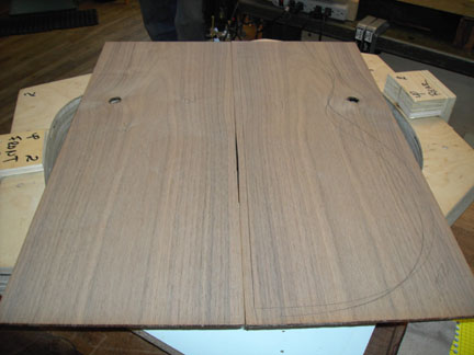 |
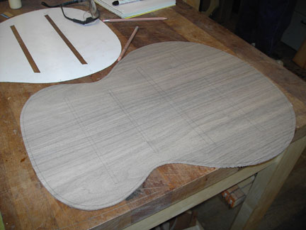
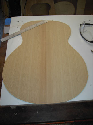
This is the walnut back that I was given. Each of us was provided very nice wood with a little interesting grain. Frank has an incredible stockpile of well aged wood! |
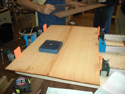 |
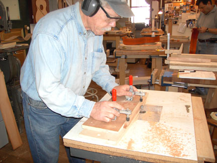
Both the top & back had to be jointed using a jointer and a bench hook with a plane or a flattened aluminum box section covered with sandpaper. Flattened means you can't take for granted that extruded aluminum as delivered from the supplier is straight (it isn't!). Frank used his granite machinists flat covered with PSA sandpaper get it flat. Unfortunately the adhesive is a bugger to get off after all the pressure. As we jointed the edge to be glued, we would periodically hold the pieces against a window to look for light leakage at the joint, then keep going till it was perfect. What you see here is Frank's current preference for joining the edges. Titebond is the glue used for most of the project. That's a 10# weight on the top |
 |
Prior to bending the sides we pre-shaped the edge which will support the back using the router table and a jig that has the shape. The bit has a shaft-mounted bearing to follow the template of the jib base. |
 |
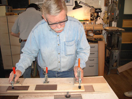
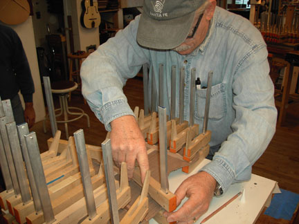
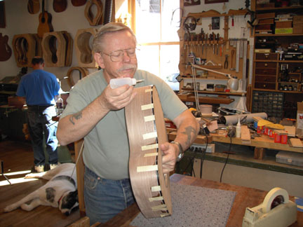
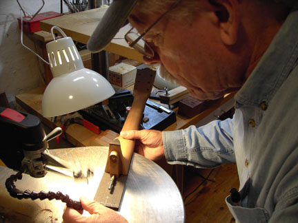
To shape the sides we used a combination of the bending iron to first get a rough shape at the waist and a start of the upper and lower bouts. The final shaping is done with a Fox-style bending machine with 150 W incandescent bulbs for the heat source. Frank's bender has the lower slat (heavier than usual) permanently attached to the pattern, eliminating the usual cross-tubes which align the sides. Here I'm getting a little practice on some scrap wood to see what it feels like. This exercise raised my admiration level of those who use this method exclusively! |
 |
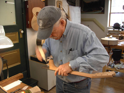
Frank demo'ing the real thing. The walnut proved to be easier to bend than material I've since used (mahogany & maple). |
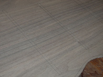 |
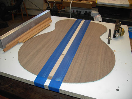
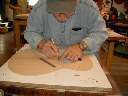
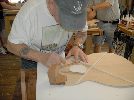
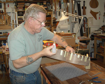
While the sides were cooking in the bending machine, we laid out the brace patterns on the rough cut back... |
 |
... using the template that Frank provided. This is a fairly stiff though flexible plastic material that was originally intended for industrial shelf liner. Probably .030" gray/white laminated material. I have no idea where to find it, bit it was a great stuff. |
 |
I'm using the router table again to cut the radius of the braces. We used a 28' radius on the top and 16' radius on the back. [ 10/2007: Frank told me recently he's changed to a 32' radius for the top of the Prima. ] |
 |
The back strip glued in place and planed. It ended up about 1/16" at the edges and about 1/8" along the centerline. It's ready for sanding. I have no pics, but we marked each brace on the back strip, then pressed a single-edged razor blade down through the strip. A chisel was used to pop out the scrap. |
 |
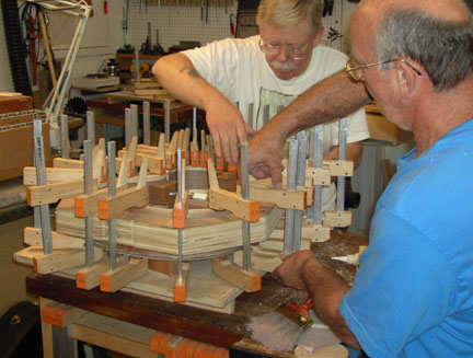
We didn't use a go-bar deck to glue the braces. After pre-fitting all the back braces into the strip we glued and clamped each brace. We had to avoid excessive clamp pressure so we didn't leave the brace glue-starved. In fitting the braces into the strip, we strove to have the brace tight enough in the strip that the back wouldn't fall off the brace when it was lifted off the table. |
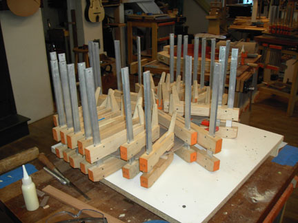 |
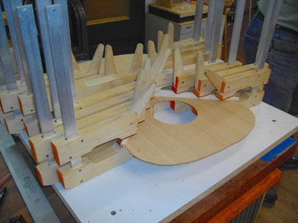
Here it is with all 4 braces clamped. While the glue was setting, we got to work on the top... |
 |
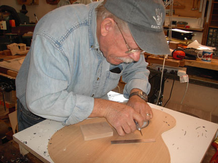
After sanding the top to thickness using the 24" reversible feed drum sander, we rough cut the top (about 1/4" beyond the sides) and marked the center for the rosette groove and sound hole. |
 |
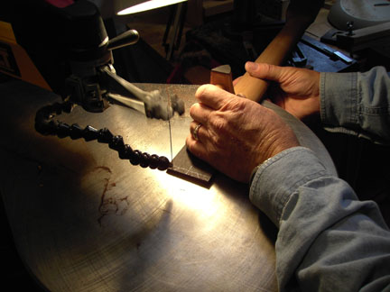
Here I am cutting the groove with the fly-cutter... |
 |
... then the sound hole. |
 |
Now inlaying the purfling and pearl. The pearl Frank supplied was pre-cut in a radius, but not the radius we used. I just broke it into pieces that would conform to the rosette radius. Only a tiny amount of filing was necessary. Once glued and sanded you couldn't see they were individual pieces without very close inspection. After the purfling and pearl were dry fit into place, the area was sprayed with accelerator before gluing with CA. The accelerator causes excess glue that spills out onto the top to cure before it penetrates the grain. Makes cleanup (sanding) an easy job. |
 |
More of the same. Afterward we used the drum sander with rough grit to bring down the purfling & pearl to the level of the top. I learned later on a top I did at home that using a fine grit heats the plastic purfling too much and smears the top. Better to use a rough grit, then finish the sanding with an orbital. |
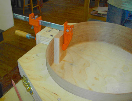 |
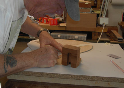
Here's the tail block being dry fit. Note the clamping caul which also serves to space the mold above the auxiliary work board and presses against the top & bottom of the rim. This is necessary since the rim extends higher & lower than the mold. |
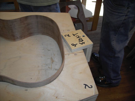 |
A look at the mold & caul for clamping the neck block. It's not apparent here, but the caul edge which contacts the rim is shaped to exactly match the mold. Hence the numbers to keep the mold + cauls in matched sets. |
 |
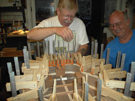
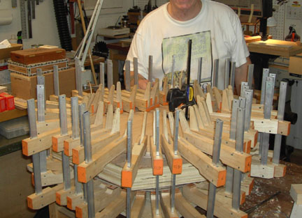
Here's the X-brace clamped. I moved a little too slow and ended up with one brace-end which wasn't attached... the glue had dried too much (I fixed it before closing up the box). Have to move quickly to get this in place and clamped before the glue skins over. |
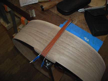 |
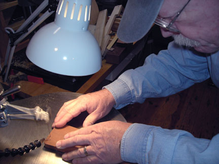
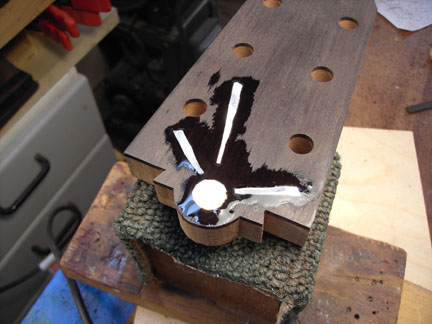
We used a jig to route the rim at the tail to hold the end graft. I saw some left-over rim material lifting from the end block, so I changed the depth and cleaned it up. Which left the cavity too deep for the material Frank had chosen (mea culpa!). Steve let me use some of his scrap padauk which turned out to be a fortuitous screw up... I really like the red wood! Btw, the padauk is nasty stuff to work with: every time sandpaper touched the stuff it was like an explosion of rust over the whole shop. Really need some good dust collection to work it! |
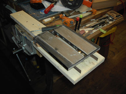 |
Here's the jig we used to cut the end graft cavity. In looking at it now, I don't see how we used it since there's no way to position the body below it... ??? |
 |
Here's the top set loosely in place before trimming the end graft and the braces and fitting the braces into the kerfed lining. |
 |
Here's the mahogany sound hole braces being fit to the X-brace and to a spare neck block. The ends of these braces fit under the wide slot in the side of the neck block tang. Frank found this is stronger than the usual 1/8" flat brace material most guitars use. |
 |
The idea was to get the braces to fit closely to the wide channel in the neck block tang. Fussy work to get it right. He had a template for setting the angle of these braces relative to the X-brace. |
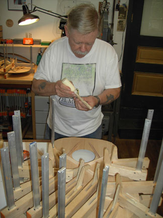 |
Here the sound hole braces have already been glued to the top. Now I'm gluing the radiused tone bars and finger braces. Every time we finished some gluing on anything we took time to clean up all glue squeeze-out. Also, when gluing, we used just the amount of glue that was necessary in order to minimize squeeze-out. The result of this extra care was that the inside looked every bit as finished as the outside. Btw, we were taught to not use water to do cleanup around the glue joints since this can weaken the joint. |
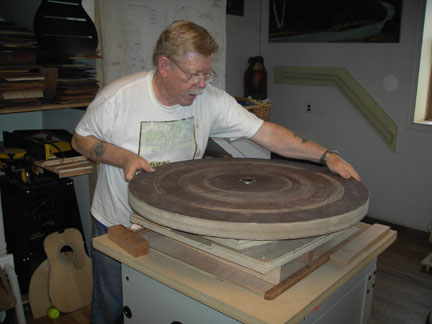 |
Using the radius dish to form the top & back faces of the rim to match (as close as possible) the now-curved top & back. The upper face of the rim above the cross brace is ground flat... no radius. This facilitates fitting the underside of the fret board without having to do blind shaping. |
 |
Here Jim is giving me a hand gluing the back to the rim. We had to move quickly so that glue didn't skin over before clamps were applied. Previous to this step I had fit the ends of the braces into the kerfed lining. |
 |
More of the same. We're having way too much fun! |
 |
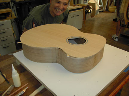
Now the top being clamped. |
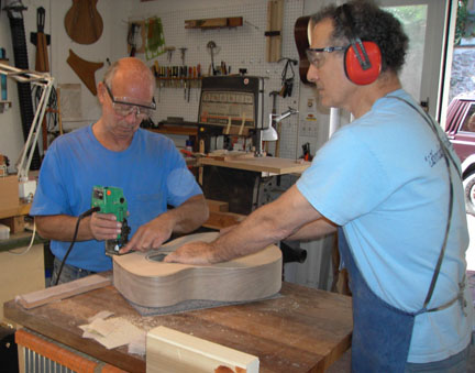 |
Jim trimming the overhang off his top. Trimming was easy on this spruce top, but on a later guitar with a redwood top, which is very hard material, I learned it can be a difficult task... or at the very least, scarey! Since the area that contacts the fingerboard (where Jim is routing at the moment) is flat and at about a 1.5 - 2 degree angle (for the neck set), this router, which has an adjustable base, had to be set to compensate for the angle. This router (made by Hitachi) is no longer available, but Porter-Cable has a laminate trimmer that is supplied with 3 different bases, one of which has an angle adjustment. |
 |
At this point I've already cut the purfling/binding slot (sorry... no pics) and laid the purfling plus binding in place. The idea here was to lay a tiny drop of thin CA glue on top of the combined pieces. The CA would then seep down into the layers of the material and bind them together and to the supporting wood. This was a process that seemed to completely evade me. I ended up with CA all over the sides. Fortunately we had previously sprayed the adjacent area with accelerator causing the CA to cure on the surface of the surrounding wood and not in the grain. It was still a mess and Frank had to bail me out with some fancy work with a drum sander. [ Frank no longer uses this approach. ] |
 |
You can see the streaks of CA following the masking tape down the sides. That of course means that the masking tape had become one with the wood. Like I said... a mess! |
 |
Frank insisted that, especially because the Martin factory was nearby, no guitar was going to leave his shop looking like a Martin! So we had to reshape the headstock somewhat to disguise the Martin-built neck we used. Here I'm using the scroll saw to cut a kiva shape into the top of the headstock. |
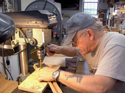 |
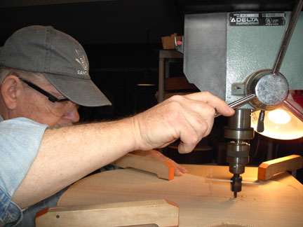
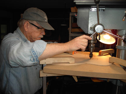
Drilling holes for the tuners. |
 |
I did a terrible job routing the headstock veneer for the pearl inlay. Frank said "Don't worry about it! You'll never see it!" He was right. Once the CA dried and had been sanded, the gaps had disappeared. |
 |
The supplied fret board, also from Martin, being trimmed to shape with more kiva steps at the sound hole. Actually, this is what kiva steps look like when woven into a rug or blanket. On pottery or on a real kiva, the steps have 90 degree angles. But I like the name, so... |
 |
You can make out the pattern on the back of the fretboard. |
 |
We were supposed to use epoxy to bond the neck & fingerboard to the body, but the test sample didn't kick off (cure). So mine was assembled with Titebond. Epoxy is preferred because it fills gaps and Titebond doesn't, The adjustment end of the double action adjusting rod (accessible from inside the body) is just visible and I'm keeping the glue away from that mechanism. Titebond, like hide glue, is heat and moisture sensitive. Assembly with Titebond means that (with a lot of work!) you can disassemble the joint for repair or resetting the neck. |
 |
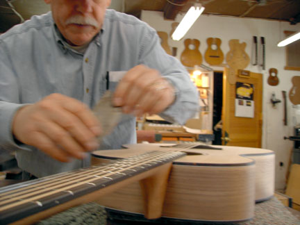
More pics & steps missing, like fretting the fingerboard and working the frets to shape. Here the neck is bonded, the frets are all set & leveled, the temporary bridge in place (using the hollow machine screws from Stew-Mac) and the guitar is strung up. The reason there were no pics is because I'd gotten behind and had to rush thru these later steps. Prior to fretting the finger board, the radius (16" as it comes from Martin) was slightly reshaped to give a conic section. It's an approximation as we used 16" (at the nut), 18" (about 1/2-way) and 20" (beyond the 12th fret) radiuses. Fret leveling was done with a sanding board that had a flattened plate glass surface. |
 |
Here I'm radiusing the tortoise binding with a scraper. |
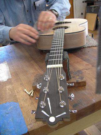 |
This shows just how right Frank was... I can't make out any of the gaps around the inlays! I'll never understand why after all these years Martin has refused to change the headstock shape so that the #3 & #4 strings have a little clearance as they cross the #2 & #5 tuning machines! |
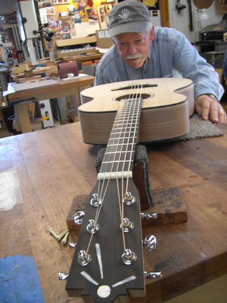 |
Looking for some more cleanup that might be necessary. If you look really closely you can see there are only 4 pegs used for the strings. That's because we used the drilled temporary mounting screws available from Stew-Mac. The bridge won't be glued till after the body is finished. |
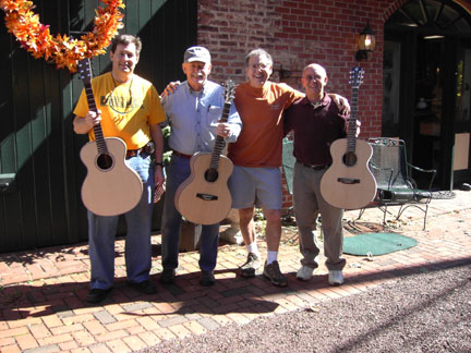 |
From the left: Steve Young (Doc), myself, Frank Finocchio and Jim Groener. Jeff wasn't able to complete his guitar. He had to get back to school (3rd graders were reportedly holding the substitute hostage!) plus he had a gig that weekend, so he was going to come back later when he could free up the time. Even though Steve worked much faster than either Jim or I, he kept volunteering to run errands for Frank in order to keep the class moving. As a result he ended up working the rest of Sunday to finish while Jim and I started finding our separate ways back home. |
At the end of the class, the guitar was built, strung and playable but without any finish. I chose to leave the guitar with Frank so that Dale Bartholomew could finish it for me. Dale did a great job (he worked at Martin for years and at one point ran the paint shop). It took a few months, but eventually the guitar found its way to Santa Fe.When it finally arrived, Celia informed me it was now her guitar! :)